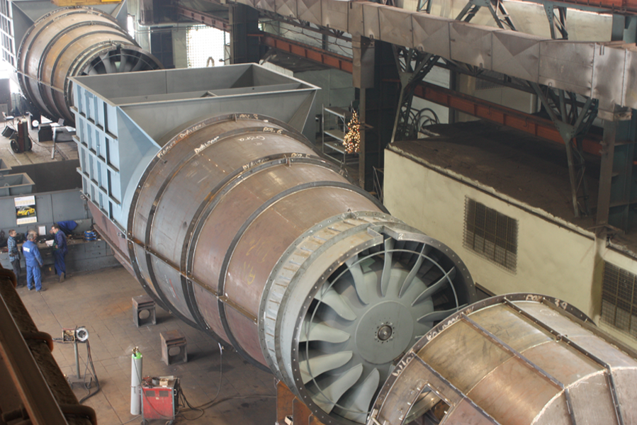
The design and process engineering divisions are equipped with the software which enables to elaborate the technical documentation necessary for commencement of the production process in due course (stress calculations, finite element analysis, 3D modelling).
The company is equipped with assorted machinery allowing us to execute most fan elements within our premises as well as to provide other services for our clients. The workshop consists of five large production halls (where are located divisions of machining and assembly), connected together, what ensures easy transportation and distribution of elements and products to different work teams. All production stands are furnished with overhead cranes of 10 ton capacity, except for the largest assembly hall where 20 ton cranes are installed.
The covered area of the workshop is ca. 10.000 m2
 . It is worth mentioning here about the tool shop where many untypical tools, instruments and devices are prepared to expedite the manufacture process. Our policy for constant improvement of quality, for meeting the market demands and for amelioration of technology results in purchasing of new machinery and in upgrading or modernising of the existing equipment.
Our aim for durable and reliable products is also associated with cooperation with science establishments like Silesian University of Technology, Foundry Institution, Welding Institution as well as world leading material and technology providers. The most important of them are FAG, SKF, Hempel, Welding Alloys, Delma-Bazalt, Castolin Eutectic, Plasma System.
Except for our typical production of fans and fan parts, we also offer execution of steel structures, services of machining and forming as described below:
|  | Welding of carbon steel, alloy steel and aluminium by means of up-to-date welding equipment like MIG/MAG with the function of impulse welding. The welding process is acknowledged by Welding Institution Gliwice and SLV |
|  | Cutting of elements from plates by means of the thermal burner – dimensions of the table 4000x12000mm. In case of using the acetylene burner, the maximum thickness of the plate is 100mm, while by using plasma burner 50mm (separating) and 30mm (quality) |
|  | Cutting of elements from plates by means of the plasma burner – dimensions of the table 2000x4000mm. By using the plasma burner in the process called HyDefinition (provided by Hypertherm company), it is possible to ensure quality cutting of steel plates of 2÷12mm thickness and typical separation cutting of steel plates of max. 16mm thickness. |
|  | Cutting of steel plates by means of the guillotine shears. Max. width 3000mm and max. thickness 20mm for steel of Rm max 300 MPa. |
|  | Straightening of plates by means of the flatteners. Max. width 2500mm and max. thickness 16mm. |
|  | Flanging on the horizontal sheet rolling machine.
|
|  | Rolling of plates on the three-high mills. Max. width 3500mm at the thickness up to 16mm for steel of Rm max 300 MPa.
|
|  | Drilling of elements on the boring machines. Max. diameter of holes: 55mm for steel and 70mm for cast iron.
|
|  | Turning of elements on the toolmaker’s lathes. Max. distance between centres is 4000mm, max. diameter of turning above the bed is 900mm and above the support is 570mm.
|
|  | Turning of elements on the CNC lathe with max. distance between centres 1500mm. Max. diameter of turning above the bed is 450mm and above the support is 300mm.
|
|  | Machining of large shafts on the heavy turning lathes with max. distance between centres 9000mm; max. diameter of turning above the bed is 1600mm and above the support is 1290mm. The lathes are equipped with special adapters for grinding of shaft journals and milling of splineways.
|
|  | Machining of large elements on the vertical lathes with max. diameter of the table 850mm or 3200mm
|
|  | Milling of elements on the boring and milling machines with the table dimensions of 1100x1400mm, 1250x1250mm; max. weight of the machined element is 4000kg.
|
|  | Milling of elements on the boring and milling machine with the table dimensions of 1400x1600mm; max. weight of the machined element is 10 000kg.
|
|  | Bending and flanging (with simultaneous holes punching if required) of cones, shrouds, nozzles, pipes made of carbon steel, alloy steel, aluminium. The process takes place on the numerically controlled bending machine type CNC FV53 NODI.
|
|  | Flanging, holes punching, reinforcement of pipes: |
| | - The special tooling that the machine is equipped with, allows to execute bending and flanging of pipes of the following inside diameter “D” 355, 400, 450, 500, 560, 630, 710, 800, 900, 1000, 1120, 1250, 1600, 2000, 2500mm. |
| | - The applied expanders allow additional calibration of a pipe, whilst execution of flanges consolidates the result. Maximum deviation of the pipe length and the flange height is ± 2mm. |
|  | Bending of pipes, cones and flat plates
|
| | - The diameters of pipes are the same as in the previous case, yet for elements made from cones or flat plates – the diameters are shown on the sketches, however the hole cannot be less than 800mm for elements of the starting angle of 0°÷45°.
|
| | - Parts can be bent in the range of 0°÷180°. Due to technological reasons, at the end of the bent part, there is always left a straight section of 20mm in length.
|

